[Mobile Internet Technology] Physical Layer in Wireless Systems
Physical Layer in Wireless Systems

Notes from RWTH Aachen University course
“Mobile Internet Technology” Summer semester 2020
professor: Drik Thißen
Physical Layer in Wireless Systems
- Radio waves
\[s(t)=A\cdot\sin(2\cdot\pi ft+\varphi)\]
\(A:\) Amplitude
\(f:\) frequency
\(t:\) time
\(\varphi:\) phase - wave length \(\lambda=\frac{c}{f},c=\) speed of light

- Frequency allocation
- ISM band (Industrial, scientific, medical)
Modulation
- Analog modulation: set parameters to an arbitrary value
- Digital modulation (Digital keying): set parameters from a finite set of values

Amplitude Shift Keying (ASK)

- Encode data with different amplitude
- needs not much bandwidth
- susceptible against distortion
Fourier Transform
Each periodic signals can be represented by a composition of harmonic signals
\[g(t)=\frac{1}{2}c+\sum_{n=1}^\infty a_n\sin (2\pi n f t)+\sum_{n=1}^\infty b_n\cos (2\pi n f t)\]
Digital modulation \(\Rightarrow\) Analog signal\(=\) periodic signal
Analog signal has infinite bandwidth
bandwidth: width of frequency band needed to represent a signal
wireless communication: restricted bandwidth


- Relationship between bandwidth and signal rate
\[S_{max}[\text{Hz,baud}]=2\cdot B[\text{Hz}]\]
\(S:\) signal rate
\(B:\) bandwidth - Nyquist Theorem relationship between signal rate and data rate
\[R_{max}[\text{bit/s}]=2\cdot B[\text{Hz}]\cdot Id(n)[\text{bit}]\]
\(R:\) data rate
\(Id(n):\) \(n\) parameters to represent \(m=Id(n)\) bits
\[\text{Data rate}\Leftrightarrow \text{Bandwidth}\]
1. Digital modulation
- analog baseband signal
- low-pass filtering
2. Analog modulation
- Shift the baseband signal to a given frequency band with carrier frequency \(f_c\)
- Bandwidth around \(f_c\) is necessary for transmission


Frequency Shift Keying (FSK)

- encode data with different frequency
- needed higher bandwidth than ASK
- bandwidth depends on \(f_1,f_2\)


Advanced FSK- MSK (Minimum Shift Keying)
- Pre-computation avoids sudden phase shifts \(\Rightarrow\) make the transition more smooth
- encode bit transitions instead of bits
even 0 1 0 1 odd 0 0 1 1 siganl h l l h value - - + + h: high frequency
l: low frequency
-: inverted signal
+: original signal

Advanced FSK-GMSK
- Gaussian MSK
- cut away high frequency side-band
- Used e.g. in GSM
Phase Shift Keying (PSK)

- more robust against distortion than ASK
- bandwidth needed


Advanced PSK- BPSK (Binary)
- bit 0: sine wave
bit 1: inverted sine wave - robust
- low spectral efficiency
- spectral efficiency: relationship between data rate and bandwidth

Advanced PSK-QPSK (Quaternary)
- Two bits coded per signal
- higher spectral efficiency than BPSK
- susceptible to distortion than BPSK
- DQPSK: Different QPSK


Quadrature Amplitude Modulation (QAM)
- Amplitude and phase modulation
- code \(m\) bits per siganl, \(m=2:\) QPSK
- \(m\) increases \(\Rightarrow\) bit error rate increase
- error rate less than PSK
- Example: 16-QAM (4 bits = 1 symbol)

Signal-to-Noise ratio
- \(SNR=S/N\)
- \[\text{dezibel[dB]:}SNR_{max}=10\cdot\log_{10}(S/N)\]
Shannon Theorem
- Noise level has influence on achievable data rate
\[R_{max}[\text{bit/s}]=B[\text{Hz}]\cdot Id(1+S/N)\text{[bit]}\]
Minimum of Shannon theorem and Nyquist theorem gives maximum achievable data rate
Hierarchical modulation to deal with noise
- DVB-T high priority stream in low priority stream
- poor reception: high priority stream (10)
good reception: low priority stream (1001)
Demodulation
- Receiver decode signal to \(0/1\)
- Problem caused by channel imperfections
- Carrier synchronization
- Bit (signal) synchronization
- Frame synchronization
- (most) interference
Antennas
- electronic signal \(\Leftrightarrow\) electromagnetic waves
- Ideal isotropic antenna: radiation pattern = circle/sphere
- Real antenna: size \(\propto\) wavelength

- best reception with wavelength \(\lambda\):
- dipole of size \(\lambda/2\)
- size \(\lambda/4\) on car roofs
- best reception with wavelength \(\lambda\):

Antenna gain
- Maximum power in direction of main lobe (葉) compare to isotropic radiator
\[g[\text{dB}]=10\cdot\log_{10} (P_{antenna}/P_{isotropic})\] - Whole input power is radiated
- the smaller radiation area, the higher the signal power
- Directed antenna

- Sectorized antenna


Antenna Diversity
- two or more antennas
- to get receiver antenna gain
- Diversity combining:
- increase strength
- construct directed antennas
- but interference

- connecting antennas with cables of different length
- to avoid interference
\(\Rightarrow\) Transmit signals with different delays causing different phases. (Through a transmitter)
Signal Propagation
Receiver Power
in vacuum \[P_r=P_t\cdot(\frac{\lambda}{4\pi d})^2\cdot G_r\cdot G_t\]
\(P_i:\) power
\(G_i:\) antenna gain
\(d:\) distance
\(r:\) receiver
\(t:\) transmitterIn reality \[P_r\propto (1/d)^\alpha\]
\(\alpha\) depends on the materialRange of received power
Distance increases \(\Rightarrow\) Noise, error rate increase
Received power influenced by
- attenuation (衰減)
- shadowing
- reflection (反射)
- refraction (折射)
- scattering
- diffraction (散射) at edges


Multipath propagation
- Signals may be directed on several paths to receiver
- Effects:
- receiver has different signal strength
- Time dispersion: signal is dispersed (分散) over time
- constructive or destructive interference
- inner-system interference (ISI)

Mobility
Quick change \(\Rightarrow\) short term fading
slow change \(\Rightarrow\) long term fading

Conclusion
reason effect Cause Multipath
Propagationfast fading fast fluctuation
positionMultipath
PropagationTime dispersion
Delay spreadSignal consists of several components
\(\Rightarrow\) ISIMovement Doppler Effect
Frequency Dispersiondistance change Attenuation Path loss especially rain and fog Shading slow fading slow fluctuation
Solution to interference, ISI, movement effects
- Antenna diversity
- Signal spreading: increase bandwidth of a signal
- Orthogonal Frequency Division Multiplexing (OFDM): reduce the signal rate but send on several well-chosen channels simultaneously
- Synchronization sequence: allow receiver to calculate signal distortion
Multiplexing
- Subdivide given spectrum for simultaneous use
Frequency Multiplex

- Separation of spectrum into smaller frequency bands
- Advantages:
- No dynamic coordination
- Works also for analog signals
- Disadvantages:
- Waste of bandwidth
- Inflexible
- Guard spaces
- Frequency division duplex
- Used for duplex communication: uplink / downlink
- two separate antennas or use a "duplexer"
Time Multiplex

- Advantages:
- Only one carrier in a medium at any time
- Throughput even high for many users
- Disadvantages:
- Precise synchronization
- Guard time (waste transmission capacity)
RTT: round-trip time
- Time division duplex (TDD)
- one frequency carrier
- uplink / downlink at different time
- Flexible: adjust time slots
Time and frequency multiplex

- Advantages:
- protect against tapping
- protect against frequency selective interference
- data rate > code multiplex
- Disadvantages:
- precise coordination
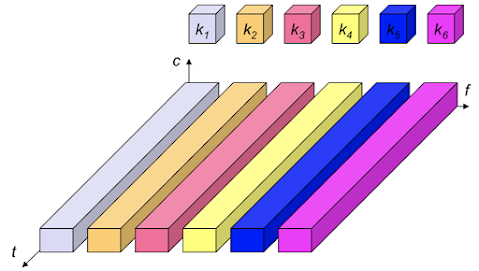
Code division multiplex (CDM)

- each channel (transmitter) has a unique code

- Advantages:
- protect against tapping and interference
- bandwidth efficiently used
- Disadvantages:
- complex signal regeneration, coordination, synchronization
- to avoid noise: orthogonal codes
\[S\cdot T=0\\ S\cdot\bar{T}=0\\ S\cdot S=1\]
Spread spectrum
- Application of CMD priciples for robust transmission
\[\text{narrowband signal}\xRightarrow[]{CMD}\text{broadband signal}\]

- Original signal of sender

- spreading to broadband \(\Rightarrow\) signal power is distributed

- \(+\) broadband interference
\(+\) narrowband interference

- Receiver reconstruct the signal \(\Rightarrow\) narrowband interference is spread

- Use band pass filter \(\Rightarrow\) remove interference


Directed Sequence Spread Spectrum (DSSS)

- \[\text{User data }\oplus \text{ Chipping sequence (random) = resulting signal}\]
- Advantages:
- Reduces frequency selective fading
- Base station can use the same frequency band \(\Rightarrow\) soft handover
- Disadvantages:
- precise power control
Near-far problem
signal near base band can wipe out signal far from base band
\(\Rightarrow\) base band has to measure and adjust transmit power

Frequency Hopping Spread Spectrum (FHSS)
- Discrete changes of carrier frequency
- Fast hopping: channels/bit
Slow hopping: bits/channel

- Advantages:
- frequency selective fading limited to short period
- Simple implementation
- Use only small portion of spectrum at any time
- Disadvantages:
- robust < DSSS
- simpler to tap
Orthogonal Frequency Division Multiplexing (OFDM)

- Variant of FDM: sub-channels are orthogonal
\(f_n\) maximum power = \(f_{n-1},f_{n+1}\) minimum power - still only one channel (merged before)
- Advantages:
- Robust against narrowband co-channel interference
- Robust against ISI
- High spectral efficiency > FDM

- Use Fast Fourier Transform (FFT)
- Low sensitivity to time synchronization errors
- Sub-channel can be adapted to dynamic channel conditions

Space Multiplexing

Limited by transmit power
Advantage:
- No coordination
Disadvantages:
- No mobility
- Only useful with other multiplexing
Cell structure
- Advantages:
- Frequency re-use
- Less transmission power
- Robust, decentralize
- Disadvantages:
- Handover
- Interference between cells
- Advantages:
Clusters
- maximum distance \(D\) between 2 cells
- \[D=R\cdot\sqrt{3k}\]
\(R:\) cell radius
\(k:\) cells per cluster

Coding
- BER: Bit Error Rate
- Packet error probability
\[P_p=1-(1-\text{BER})^n\]
\(n:\) bit length - How to deal with high BER?
- Error detecting code
- CRC
- Error correction code
- Block error correction:
- Hamming code
- BCH code
- Reed-solomon code
- Convolutional code
- Trellis code
- Turbo code
- Block error correction:
- Error detecting code
Block code
- process blocks of data independently
- \((n,k)\) protect \(k\) bits data with \((n-k)\) FEC-bits
- ex. \((255,247)\)
- Disadvantage:
- large \(k\) causes expensive calculations periodically
- convolutional code: generate redundant bits continuously
Convolutional code
- Dispere (分散) each bit over time
- \((n,k,K)\)
\(K:\) constraint factor (“memory”)
\(n=f(k,K)\)
\(n\) bits output depends on \(k\) and \(K-1\) input bits - Example

- \(V_{n1}=u_{n-2}\oplus u_{n-1}\oplus u_{n}\)
\(V_{n2}=u_{n-2}\oplus u_{n}\)
\(V_i:\) output bits
\(u_i:\) input bits (state)
- \(V_{n1}=u_{n-2}\oplus u_{n-1}\oplus u_{n}\)

Trellis Diagram


- Hamming distance
\[d\geq2\cdot t+1\]
code can correct \(t\) errors - Search trellis for possible paths
Viterbi Algorithm
- Check if received string gives a valid path through trellis
- Calculate hamming distance, choose the shortest path
- High complexity
Turbo codes
- Faster decoding > Viterbi Algorithm
- RSC codes: recursively systematic convolutional codes

- systematic: input bit taken over as output bit
- take interleaved bit sequence
- guess missing check bit (or set to 0)


留言
張貼留言